Ladda ner presentationen
Presentation laddar. Vänta.

1
EcoPart 400 6 – 34 kW

2
Design & dimensions Front panel – 2 screws Pre-cut holes for flexible tubes Adjustable feet

3
Design & dimensions

4
Brine connection 4 flexible tubes included mounted from factory All direction compliant Water IN Water OUT Brine Sole IN insulated Brine Sole OUT insulated

5
Brine connection Insulated Tested with water in factory Inside the product

6
Power output In the same dimension

7
COP – Noise level COP 0/35 EN14511 Sound Power *EcoHeat ”old” 300 Mätningar enligt EN3747 vid 0/35. Värden gäller både 400V och 230V.

8
Noise level Compressor cover New quality insulation

9
Other options Filling kit for sole / brine Charging pump – accesory StratosTec 25/6 StratosTec 25/7 25/8,5

10
Electrical box Soft starter card Control system for HP Accessible from front Also EcoHeat 300

11
Electrical installation Cabling SEPARATE Bus and Supply

12
Control system Various options BasicDisplay EcoLogic V3 EcoEl V3 EcoZenith i550 Ecologic PRO CTC Interface

13
Basic Display

14
Control system Basic Display for fixed temperature –Short parameter list Return temperature setpoint Differential on / off Reading of the temeratrure Reading of the pressur Set the heatpump number for cascade –Alarm handling –Needed for casade application

15
DisplayNameDescriptionEcoair, Ecopart 101Operation modeIf mode is Fix return stop, display shows set-value for stop temperature, other modes are displayed with corresponding letter A1, A2, A3 … A10 EA + EP 102Start stop difference Only in Fix Return Stop Mode. Other modes do not show this display.EA + EP in fixed return stop mode 103DischargeMeasured discharge temperature is shown here.EA + EP 104Outdoor Temperature Measured outdoor temperature is shown here.EA 105Last error / present error Displays the last / preset alarm with the letter “E” followed by the corresponding error code EA + EP 106Brine out tempMeasured Brine Out temperature or Exhaust air temperature is shown here.EA + EP 107Brine in tempMeasured Brine In temperature is shown here.EP 108Inlet tempMeasured Inlet temperature is shown here.EA + EP 109Outlet tempMeasured Outlet temperature is shown here.EA + EP 110Suction tempMeasured Suction temperature is shown here.EA + EP 111High PressureMeasured Pressure in bar in high pressure side is shown here. Special function: If up + dn is pressed for 3 seconds in this menu and product = EA -> start a defrost. The defrost should then run and stop according to its function description. EA + EP 112Low PressureMeasured Pressure in bar in low pressure side is shown here.EA + EP 113Evaporation CMeasured Evaporator temperature from low pressure conversion is shown hereEA + EP 114Condensing CMeasured Condensing temperature from high pressure conversion is shown here EA + EP 115Suction SHSuperheat is shown hereEA + EP 116EV %Expansion valve opening is shown hereEA + EP 117Capacity KWCapacity from heat counter function is shown here.EA + EP 118Current ACurrent (from soft starter) is shown hereEA + EP 119Defrost TimerTimer defrost is shown hereEA
 is shown hereEA + EP 119Defrost TimerTimer defrost is shown hereEA.")
16
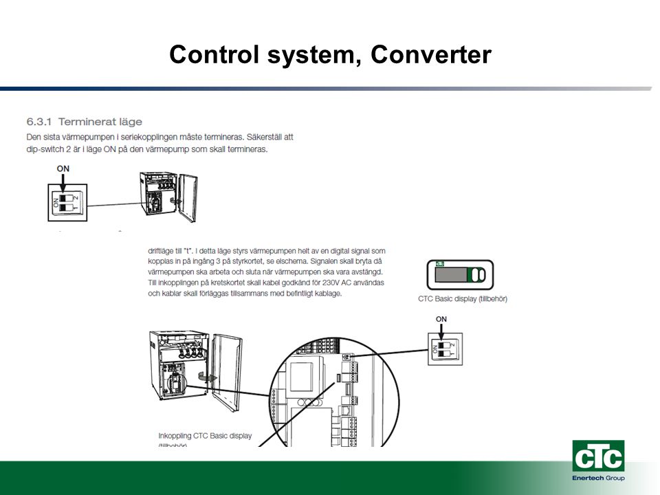
Basic Display 7.2 Larmutgång EcoPart är försedd med en potentialfri larmutgång som aktiveras om något larm är aktivt i värmepumpen. Denna utgång får kopplas till en maximal last på 1A 250V AC. En yttre avsäkring bör också användas. För inkoppling av denna utgång ska kabel godkänd för 230V AC användas oavsett vilken last som ansluts. För information om inkoppling se elschema. 7.4 Termostatstyrning Värmepumpen kan köras med termostatstyrning. För att detta ska aktiveras behövs tillbehöret CTC Basic display. I CTC Basic display ställs då driftläge till ”t”. I detta läge styrs värmepumpen helt av en digital signal som kopplas in på ingång 3 på styrkortet, se elschema. Signalen skall bryta då värmepumpen ska arbeta och sluta när värmepumpen ska vara avstängd. Till inkopplingen på kretskortet skall kabel godkänd för 230V AC användas och kablar skall förläggas tillsammans med befintligt kablage.

17
Control system, Converter Ecologic V3 & EcoEl V3 + CTC Converter Cable connection between EcoPart and Converter Wall mounted Use of the 12 systems in EcoLogic CTC Converter

18
Converter

19
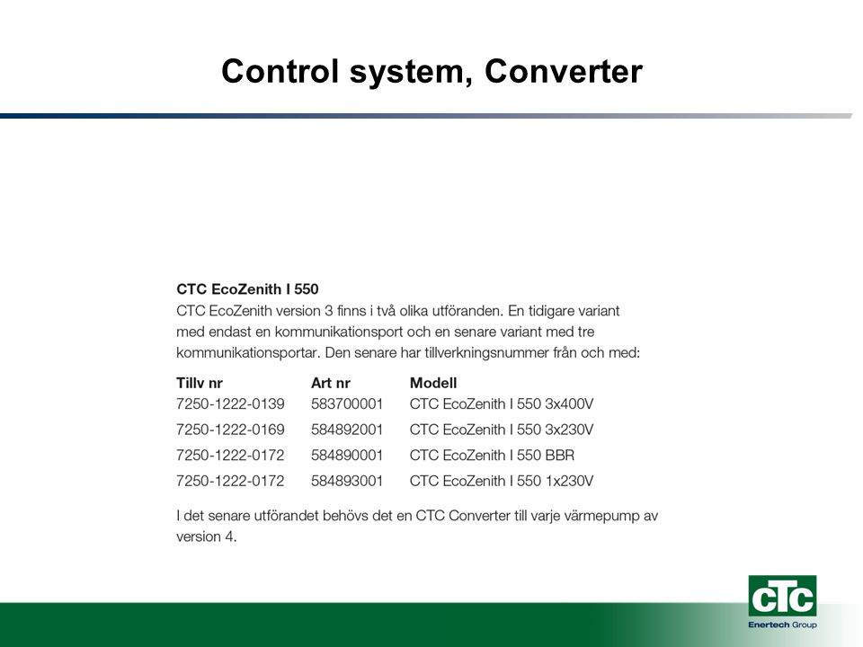
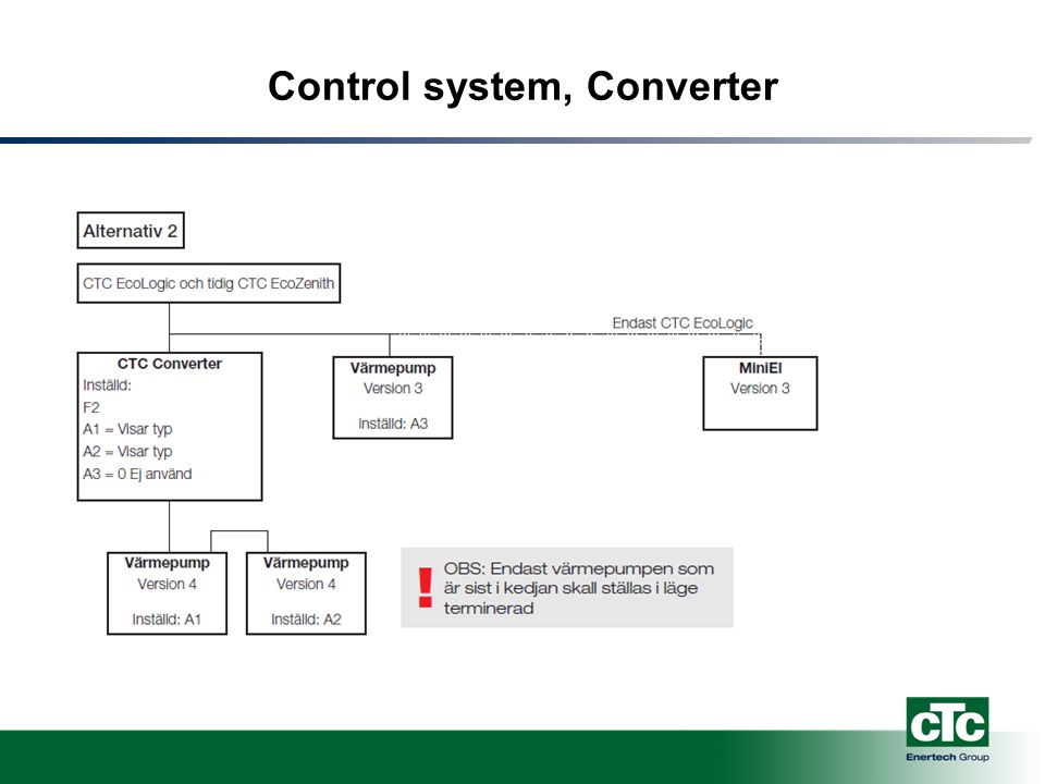
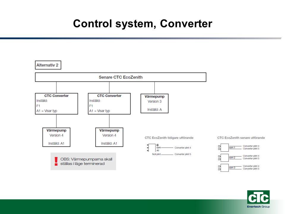
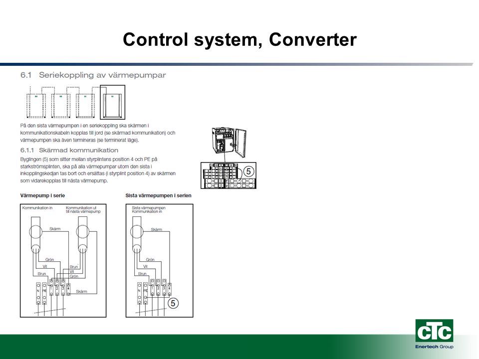
Control system, Converter

26
Control system Next step – CTC EcoLogic PRO Use of 6 systems See Ecologic presentation

27
Next step EcoPart XL EcoPart 424 EcoPart 434

28
EcoPart XL Performance

Liknande presentationer